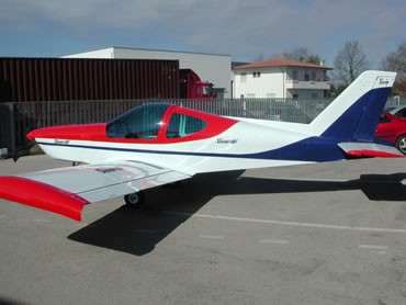
Longer than other StormÆ models (12 inches more
than 300), the fuselage of Storm 500 consists of two basic
sections: the first section includes landing gear beam, wing beam
and cabin section, and the sheet-metal tail cone section. The
landing gear bolts on to the assembled fuselage section. The all
sheet metal fuselage is a conventional semi-monocoque structure: a
basic rectangular section formed by four longerons, with skins
blind riveted to the longerons (and stiffeners). Two rounded
bulkheads form the top skin. The cabin area of the fuselage is
unique in many ways. It was designed for todayÆs pilots who are
significantly taller than pilots were 50 years ago. A typical
six-foot six-inch pilot will sit comfortably with plenty of head
room to spare even while wearing headsets. Visibility is excellent
through windows. The front seats are positioned near the front of
the wing so that the downward visibility to the ground is
excellent.
The cabin width is an amazing 43 inches from window to
window and higher 2 inches than other Storms, making it the widest
cabin in its class. The adjustable back seats support fold forward
to allow access to the rear seats. Two inspection holes are
located under the seats for easy access to the spar for wing
removal. The aircraft seats are very comfortable even after a 5
hour trip thanks to the special foam that adjusts its shape. The
seat belts are easy to adjust and require no maintenance. The
Storm 500 wing design has a thicker wing section than other Storm
models. A thick cantilever wing provides maximum strength at
minimum weight. It is also aerodynamically efficient since there
is no drag-inducing exterior bracing. The wing has a high lift
airfoil and wing tips to maximize the Storm 500 effective wing
span.
The wing is of all-metal stressed-skin full-cantilever
low-wing design consisting of two wing panels bolted to a spar box
assembly in the fuselage. The cantilever wings are attached to
each side of the fuselage by insertion of the butt ends of the
main spars into a centre spar structure which is an integral part
of the fuselage. The rear wing attachments introduce the wing
torsion and shear into the fuselage. The main spar structure
provides in effect a continuous main spar with splices at each
side of the fuselage. Thanks to the high strength of this spar, a
relatively low number of wing ribs and stiffeners is needed, thus
simplifying construction. The efficient use of parts in the design
limits the number of parts required, reducing assembly and
maintenance times. The wings are not tapered and have no "twist,"
making them easy to build and maintain. Two separate spars make up
each wing with the main spar being in 25% from wing leading edge.
The two spars are fastened to the fuselage by means of AN bolts,
making the wings easy to remove. The main spar is made up of
eleven 2024T3 plates solid riveted to a web, similar to an "I"
beam. At the wing tip, the Storm 500 design utilizes tips to
maximize the wingÆs effective lift area and to minimize wing tips
vortices. Storm wing tips provide the largest effective span for a
given geometric span or a given wing weight. The ailerons and
flaps make up the wing controls. The ailerons are made of formed
aluminium skins held in place with ribs. They are light, easy to
install, and have counter balance weights. They are connected to
push/pull rods which are connected to a simple bellcrank in the
wing. Control cables are connected between the bellcrank and the
fuselage torque tube, which is connected to the yokes. The
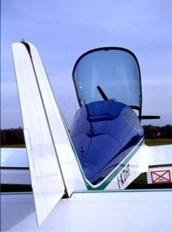
empennage (tail) of the new Strom 500 demonstrates the design and
construction efficiency of S.G.Aviation. The tail is comprised of
a single horizontal tail (stabilator) and a single vertical tail
(rudder).
The stabilator is dynamically balanced and mounted to the fuselage
with two large steel bearings. Operation of the stabilator is
through the push-pull movement of the control wheel yoke control.
The "flying tail" stabilator is equipped with dual trim tabs
(interconnected) mounted on the trailing edge. The trim tab is
actuated by an electric trim motor, which is activated by the
pilot by moving a electric trim wheel, similar to conventional
aircraft. The stabilator construction is a conventional semi-monocoque
structure. Individual aluminium ribs riveted to a large box type
spar enclosed in aluminium skins make up the stabilator. The one
piece control surface does not have any moving parts other than
the dual trim tabs which are piano hinged at the trailing edge.
The stabilator control cables are adjustable through the large
access panel under the rear fuselage bottom. Like all Storm
models, the Storm 500 features an all-flying vertical tail
(rudder) section for excellent effectiveness and control,
especially at low speeds.
The all-flying rudder provides
responsive rudder control, while also minimizing weight and
complexity (thereÆs only one vertical tail section). Two rudder
bearings bolt to the rear fuselage to fix the rudder to the
fuselage. The rudder is dynamically balanced by a small weight
installed in the leading edge. Operation of the rudder is through
the movement of the rudder pedals. The rudder is "self centring"
in flight through the nose wheel strut bearing. Construction of
the rudder is a conventional semi-monocoque structure. Individual
aluminium ribs riveted to a simple "U" channel spar enclosed in
aluminium skins make up the rudder. The one piece rudder control
cables are connected with turnbuckles to the rudder which can be
adjusted from the outside of the aircraft. The "self centring" and
easy to adjust cables eliminate the need for a fixed rudder trim
tab. The heavy-duty tricycle gear system was chosen as the
standard gear configuration for the Storm 500 to meet the needs of
todayÆs pilots: Most pilots are not experienced ætaildraggerÆ
pilots, and a tricycle gear provides better stability and control
on the ground.
Borrowed from the Storm 300, the Storm 500 utilizes a heavy duty
gear system developed specifically for flight training operations.
The main gear is a 2 aluminium springs that provide double
cantilever deflection. Four large bolts for each side hold up the
2 springs to a fuselage beam inside.
It provides excellent grass-field capability, and is very durable,
simple and virtually maintenance-free. The nosewheel strut uses a
single heavy-duty bungee for shock absorbency. The nosewheel is
steering, with direct linkage to the rudder pedals for very
effective and responsive ground handling and tight turns. The main
wheels are equipped with hydraulic disk brakes.
The Storm 500Æs gear has been developed to allow grass-field
operation, and the direct linkage steering nosewheel, provide
remarkably precise ground handling and steering.
The brakes are actuated by toe brake pedals which are attached to
the rudder pedals. The master cylinders with reservoirs are
connected to the pedals on the pilot side, and standard master
cylinders are on the passenger side. No additional brake fluid
reservoir is used. Brake lines are made of clear heavy duty nylon
tubing. This makes it easy to bleed the brakes and very easy to
install and remove the lines.
The nose gear is steering through a 22░ degree arc each side of
centre by the use of the rudder pedals. Steel 3/8 inch diameter
rods connect the rudder pedals to the nose wheel. This gives the
aircraft accurate and tight steering. The nose wheel design is
unique in that it is very simple. The nose wheel strut is held in
place with two large nylon bearings, impregnated with oil. The
lower bearing is machined so that the strut "self centres" which
also centres the rudder. The nose wheel is attached to a Š inch
thick aluminium wheel fork which is bolted to the nose strut. The
nose strut is 2 inch diameter 4130N steel tubing. The result is an
all around extra tough nose gear assembly which has no O rings,
back-up rings or gaskets. Additionally, no shimming is required.
specifications
powerplant
propeller
length
height
wing span
wing area
seats
empty weight
useful load
gross weight
fuel capacity
range |
140 -180 HP
x
23.7 ft
x
28.2 ft
122.2 sq. ft
4
1122 lbs
x
2145 lbs
47.6 gal
715 sm |
performance
takeoff distance,
ground roll
rate of climb
max speed
cruise speed
landing distance, ground roll
service ceiling |
722 ft
1476 fpm
180 mph
172 mph
820 ft
x |
limiting and recommended speeds
design manoeuvring speed (Va)
never exceed speed (Vne)
stall, power off (Vsl)
landing approach speed |
x
199 mph
53 mph
x |
All specifications are based on manufacturer's
calculations
|