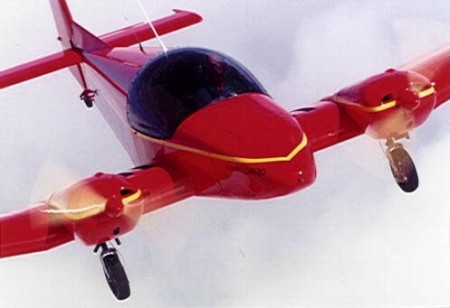
The GEMINI CH 620 is a light twin-engine
kit aircraft. The sleek low-wing design has a wide performance
envelope, making it easy to fly (low landing speed), yet it
outperforms most other light aircraft in its weight and power class.
The aircraft features a simple retractable gear system, available in
either standard taildragger or optional tricycle gear configuration.
Basic features of the GEMINI include a high
useful load, large cabin area, and ample baggage space, making the
light twin aircraft suitable for extensive cross-country trips, yet
simple and sporty for local recreational flights.
The GEMINI provides comfortable two-place
side-by-side seating in a spacious 44-inch wide cabin. Access to the
cabin is easy from both sides of the aircraft, facilitated with
20-inch wide reinforced wing walkways on either side of the
fuselage. The large bubble canopy provides outstanding visibility,
including superior forward-downward visibility that only a
twin-engine aircraft can offer.
The large cabin area is equipped with a
full-size instrument panel for basic flight and engine instruments.
There is plenty of clearance behind the panel to accommodate full
custom avionics packages.
DUAL CONTROLS: The GEMINI features a
centre-mounted
control stick accessible from both the left and right hand seats.
The unique "Y" control column is a Heintz design feature that pilots
fall in love with - it leaves the occupants lap area unencumbered -
unlike dual yoke or stick controls - leaving room for charts or
other navigation aids on the pilotÆs or co-pilotÆs lap. The centre
stick also does not restrict visibility and access to the instrument
panel.
The engine controls quadrant is situated on
the left hand side of the cabin for easy access to the pilot. The
dual rudder pedals also provide steering for the nosewheel (in
tricycle gear configuration) or the tailwheel (in conventional
configuration). Standard toe-brakes provide differential braking to
the hydraulic disk brakes.
DESIGNED FOR EASE OF CONSTRUCTION
The GEMINI CH 620 is designed not only to
provide excellent performance and flight characteristics, but
importantly, also for quick and easy assembly from Zenith AircraftÆs
complete kit. The aircraft uses single-curvature sheet-metal skins
fastened over structural members, such as the factory-manufactured
spar, wing ribs, longerons, and fuselage bulkheads. Parts are
fastened using the proven Avex blind rivets, which are as easy to
set as æpopÆ rivets. The corrosion-resistant Avex rivets provide a
permanent structural bond and tight low-profile domed finish formed
by the custom riveter head.
Blind riveting does not require the special
skills or tools that conventional "bucked" riveting calls for,
making it well suited for first-time builders. Additionally, as the
name implies, riveting is performed only from one side, with access
to the æblindÆ side not required. Because the Avex rivets are so
easy to set, construction time is minimized.
MODULAR CONSTRUCTION: The GEMINI is
assembled one section at a time to minimize space requirements while
building. Typically, the wings and tail section are built first.
Once assembled, these sections may easily be stored until theyÆre
ready to be joined to the fuselage. Even the fuselage is built in
two sections to minimize the space needed to build the GEMINI. The
modular building sequence allows the builder to "buy-as-he-builds"
rather than buying the complete kit at once.
The GEMINI CH 620 wings are made of a
carry-through cantilevered main spar. The wing centre-section has a
thick 18-percent constant chord airfoil, with tapered outboard wing
sections. The outboard wing panels are made for quick and easy
removal from the centre section, and are fitted with full-length
ailerons at the trailing edge. A sophisticated factory-welded
chrome-moly steel device acts as an integrated engine mount and
retractable landing gear assembly, attached at each end of the
centre wing section.
The rear fuselage is made up of a simple
rectangular section with a rounded top, formed with single-curvature
skins with internal longeron and bulkhead reinforcements. The cabin
area is built around the centre wing section, and rounds at the
front to join the sleek fibreglass nose cone.
The conventional horizontal tail has a
fixed stabilizer and large elevator, equipped with a standard
electric trim tab. Fiberglas fairings round the ends of the
horizontal tail. The full-flying vertical tail (rudder) is all
moving to provide maximum cross-wind capability.
The rugged retractable landing gear may be
configured either as a taildragger (conventional) or tricycle
(optional). The main gear is equipped with large 16-inch wheels and
the sturdy retractable gear mechanism uses dual æbungeeÆ shock
absorbers to provide rough field capability. The main gear is
mechanically retracted by a lever located in the cabin. The
low-profile tailwheel is fixed (non-retractable), and is linked to
the rudder pedals for effective ground handling and steering.
The all-metal airframe design is based on
the ZODIAC CH 601 kit series and other Heintz designs which have
proven themselves exhaustively over the past 22 years.
THE GEMINI CH 620 KIT
Developed for the novice builder, the
GEMINI kit draws on ZenairÆs vast aircraft design and manufacturing
experience. Over the past twenty two years, Zenair has excelled in
the light aircraft industry, successfully bringing to market more
than 12 new kit designs and a type-certificated production aircraft.
Being the latest Zenair development, the GEMINI CH 620 kit brings
forward the ZODIAC CH 601Æs tried and proven kit building technology
developed for novice builders.
The main wing spar is made up of three
sections: A fuselage centre section and the outboard wing panels.
The three sections are bolted together for easy disassembly.
The sturdy wing spar is a built-up C-beam with spar cap angle
extrusions buck riveted to the shear web. Spar cap doublers are
added at the top and bottom of the web at the wing root. The spar
sections are joined by dual splice plates that set the 6Į-degree
wing dihedral. In the kit, the spar sections are
factory-manufactured and jigged together.
WING ASSEMBLY: Building the wing
sections is easily done on a flat workbench (about 12Æ x 4Æ). The
nose and rear wing ribs are positioned to the pre-drilled stations
along the spar. The pre-formed wing ribs are supplied
ready-to-install (hand finished with flanged lightening holes). A
rear spar "Z" angle is attached to the ends of the rear ribs. Once
the wing "skeleton" (internal assembly) is put together, top and
bottom rear wing skins are fitted to the assembly. The pre-formed
leading edge skin is then simply wrapped around the nose ribs and
fastened together with the rear skins and spar.
Welded aluminum wing tanks are installed
behind the main wing spar in the outer wing panels. The ailerons are
made up of a single pre-formed sheet-metal skin, with internal
reinforcement ribs. The top aileron skin is fastened to the rear
wing, providing a unique and simple æhingelessÆ gap-sealed pivoting
system.
TAIL SECTIONS: The horizontal
stabilizer structure is made up of two spar sections with eight
internal ribs. A single pre-formed skin is then wrapped around the
assembly for final covering. The elevator uses a single pre-formed
skin with several internal rib supports. The elevator is hinged to
the stabilizer with a convention piano-hinge. A standard electric
trim servo is mounted inside the elevator.
The tapered rudder (vertical tail) consists
of a main spar that runs the length of the rudder, with nose and
rear rib supports. A single rear skin is overlapped by a pre-formed
nose skin, riveted together at the spar.
FUSELAGE CONSTRUCTION: The fuselage
is assembled in two manageable sections: the rear fuselage and the
forward fuselage / cabin area.
The rear fuselage is built up on a flat
workbench, by first attaching longerons, stiffeners, and support
brackets to the pre-formed bottom fuselage skin. The flat side walls
are also built up from a flat workbench, and then joined to the
fuselage bottom. The top rounded bulkheads are then attached to the
bottom-half assembly and the top fuselage skins are placed around
the bulkheads.
The forward fuselage / cabin area is built
up around the wing centre section, positioning the cabin side skins,
cabin floor, and nose cone bulkhead. The instrument panel and cabin
frame are then attached to the section. The two fuselage halves are
then fitted and joined together.
Once the major airframe sections are
assembled, the landing gear is installed: the integrated engine
mount and retractable landing gear assembly is bolted to each end of
the centre wing section (fuselage), and the wheel assemblies are
bolted to the bottom of the landing gear struts. The tailwheel
assembly is bolted to the end of the rear fuselage.
With the fuselage on its gear, the tail
sections and the outer wing panels are bolted to the fuselage, and
the controls are installed: The factory-welded rudder pedal
assemblies are bolted to the cabin floor, and the centre stick is
installed. Cable control lines are then run through the fuselage to
the tail sections and attached to the elevator and rudder control
bellcranks, and aileron control cables are brought to the aileron
bellcranks at the ends on the centre wing section. Pushrods connect
the bell cranks to the ailerons.
The formed Plexiglas bubble canopy and
frame is then assembled and fitted to the fuselage. The engines are
fastened to the airframe, and powerplant controls and systems are
installed. Finally, the fiberglass engine cowls and the nosebowl are
fitted to the completed aircraft.
The complete kit has been developed to meet
the "51% rule," making it eligible for "Experimental - Amateur
Built" registration in the United States. Contact the Federal
Aviation Administration (FAA) for details on kit aircraft
registration and operation.
Assembly time for the complete kit is
estimated at just 750 hours for the average novice builder. That
means that the average builder can expect to fly the completed
Gemini within just one year when averaging about two hours of
building time per day (or slightly more than three months
full-time).
WORKSHOP SPACE: A basement workshop
or single car garage provides plenty of room for most assemblies.
All the sections are built on a flat level workbench (12Æ x 4Æ). No
requirement for temperature controlled workshop.
TOOLS: Only simple hand tools are
needed. This also means that no special building skills or
experience is needed, making this a good project for first-time
builders. Parts or processes that require special tools, jigs or
skills are pre-manufactured at the factory to minimize the
construction time.
- Basic tools required for assembly
include:
-
Hand (or pneumatic) blind riveter with
custom domed heads;
-
Cleco temporary fasteners
-
Sheet-metal snips
-
Hand drill (electric or pneumatic)
-
Assorted hand tools such as files,
pliers, wrenches, etc.
No costly or specialized tools are
required, and importantly, no jigs or fixtures need to be made (that
means time is spent building the aircraft, and not making jigs).
specifications
powerplant
propeller
length
height
wing span
wing area
seats
empty weight
useful load
gross weight
fuel capacity
range |
Jabiru
2200
80 hp
fixed pitch 55-IN dia. ground adjustable
19
ft
5
ft10
ins
27
ft 3
ins
123
sq ft
2
800
lbs
650
lbs
1450
lbs
4 US gal
650
miles |
performance
takeoff distance,
ground roll
rate of climb
max speed
cruise speed
landing distance, ground roll
service ceiling |
450
ft
1280
fpm
155+
mph
145
mph
450
ft
12,000+
ft |
limiting and recommended speeds
design manoeuvring speed (Va)
never exceed speed (Vne)
stall, power off (Vsl)
landing approach speed |
x
x
x
x |
All specifications are based on manufacturer's
calculations
|