Over the years I have seen some pretty homebuilts and some even nicer
production planes, but if one should look closer and peek underneath the
control panel, the truth is normally revealed regarding the competency of
the builder or service organisation maintaining the production plane.
The electrical wiring on most of these planes leaves much to be desired,
whether homebuilt or other. As a homebuilder involved in quite a number of
projects over the past 15 years, I have picked up the skills to assist
most of the homebuilding fraternity in SA with advice regarding how to do
the electrics, avionics and intercom systems on their planes.
One would expect aircraft wiring to be
complex, well, let me inform you that the technology used in aircraft
mostly dates back to the 50's and 60's, (and even before that!!) and that
only the very wealthy can now days afford the state of the art technology
for homebuilts and they are most probably not into homebuilding anyway.
So, that leaves you with the only choice and that is to do all the wiring
and radio/avionics installations yourself.
planning your wiring

Before
one rushes off to the local hardware shop, buy some wire, a couple of
fuses etc and attempt to start wiring you plane, there is a lot of
planning that you have to do.
Firstly, you need to know what
electrical equipment you will be installing in your aircraft and you will
have to sit down and plan your wiring diagram and the relevant
component/parts ratings. There are plenty of good books and articles in
various aircraft magazines on how to do this.
My intention is not to repeat all that
good work in this article, but to assist that you do not make unnecessary
costly or "ugly" mistakes. One of the ugliest things that you can do to
your airplane panel is not allowing enough room for spare circuit breakers
and switches and you then have to add afterwards onto a secondary panel or
even worse scatter the breakers and switches all over the show. You will
also have to make a decision on whether you will have one electrical bus
or two. I now days recommend that you have a main electrical bus and a
radio/avionics bus. The reason for this being that you now have a choice
to install a "radio" master switch in between the two busses. This feature
is very handy during start up and shut down, as one switch "kills" all
avionics and you don't have to change volume settings etc.
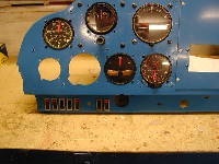
Another
thing that you will have to decide during your planning session is where
on your control panel you will be housing the switches and circuit
breakers, as well as your indication lights, voltmeter, and ampmeter. Yes,
I recommend both a voltmeter and ampmeter. These instruments are fairly
cheap and can save you a lot of grief once you realise their potential.
Another
must is that you retain control over your alternator field, so you will
need a switch to switch off your alternator field. The voltmeter will tell
you whether your voltage regulator is working properly (13.8 V to 14.2 V)
and instead of blowing your expensive radios if the voltage regulator goes
faulty (usually results in an over voltage), you can switch off the
alternator field and revert to battery power. ( Seeing that it is not that
easy to switch off your engine in order to save the radios when you are
flying!)
designing your control
panel
Now gentlemen
(and ladies), most of the aircraft that I have worked on so far are fairly
cramped underneath their control panels and I am over 6 ft tall. If you
fall into that category as well, do yourself a favour and design your
control panel with drop down panels for everything - What do you mean, you
will say? What I am hinting at, is that you design your panel with a back
skeleton base and loose panels that will fasten from the front by means of
screws and rivnuts (if you don't know what rivnuts are let me know and I
will do an article on them as well) So, have a panel that you can sit
comfortably in your pilots seat and work on everything, by loosening the
various panels and secondary panels and dropping those into your lap!..
yes, you have guessed right, you have to leave enough slack in the wiring
to do just that . (Another advantage is thus that you don't wake up with a
severe back ache on the Sunday morning)
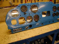
My
recommendation be that you have at least the following individual dropdown
panels; flight instruments, electrical switches and magneto switch, engine
instruments, radio stack, circuit breakers (heavy current stuff like
landing lights, navigation etc), separately from that of the avionics
circuit breakers. Once something goes wrong (and it does - believe me) you
can quickly remove the culprit panel and fix it. (presumably not in
flight!!!).
What you have probably realised from the
above is that you can not really do the planning of the wiring on your
aircraft in isolation and that there are many factors like panel design
that you also have to consider right from the onset. Please do yourself a
favour and get a big enough piece of cardboard and draw your control
panel, instruments, switches, circuit breakers, pull knobs etc actual
size. You will in that way find whether you can in fact reach a particular
switch for instance, in flight without ducking you head underneath the
panel (and entering a spin, should you not be careful.)
To
properly plan your layout you will also need the actual sizes of all the
components that you want to accommodate on the panel. Now is also a good
time to start acquiring all these components. Make sure that you find
circuit breakers or fuses with the correct ampere ratings. If you can't
find the correct aircraft quality components you may use ordinary
commercial stuff, but please test these to destruction and if the rating
on a switch says 10 A, limit what you want to break to only 50% of that. I
have found rocker switches which are commercially available for an
electrical stove, to be quite robust and that the contact gap once open,
is quite wide, which is good for spark quenching purposes.
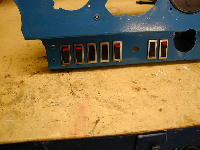
In the photographs you will see the
rocker switches that I have used on the Piper Tripacer that I am busy
restoring. I have also made sure that there will be no confusion whether a
switch is switched on or off.
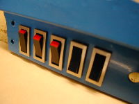
As
pilots I know you are not colour blind, so you should be able to spot the
switches which are turned on. Please note that the current ratings given
for these switches will be for AC and that it is more difficult to break
DC, hence you have to test samples of the component types that you intend
using to destruction.
If you find that you want all your
switches to look similar, but the landing light for instance consumes more
amperes than the switch can withstand, don't despair, just employ a slave
relay of the correct contact rating for that circuit.
summary
Well, Now you should have the following
wrapped up; Your wiring diagram, with bus choices and circuit ratings
showing all the devices (loads) you will be installing as well as the
spare slots. Your panel layout, ie. Switch positions and type, circuit
breaker panels, volt and amp meter positions and a general full scale
panel drawing.
All your switches, circuit breakers,
volt and amp meter all tested and physically in hand.
general
Now
that you have your planning complete, it is time to seriously get all the
components and tools together. As promised, here is the second article on
wiring. It will really pay to invest a little in the correct tools and
methods on wiring. The tools that you require to do wiring are not very
expensive and I therefore recommend that you purchase these.

Either way you will have to ensure that,
firstly you perform a proper job and secondly that when you have to add to
your wiring you do so in a consistent manner. Let's discuss the tools
first.
tools required to do wiring
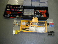
I
have a long time ago decided that I will buy a plastic toolbox for wiring
purposes only and this has worked well over the years in the sense that it
has "kept everything together". The advantages of this box being that I
don't have to hunt around for my stuff should I want to perform a wiring
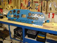
job. In the attached photographs you will get an idea of what I have done
and how I have grouped everything. So, What do you have inside this
toolbox one may ask?
Well, it is a combination of tools and
essential consumable wiring spares. Inside I have, two soldering irons,
big and small, solder, wire insulation strippers, long nose pliers, side
cutter, soldering flux, heat shrink insulation of various colours, lengths
and sizes, wiring letters, spare switches, spare relays, cable straps of
various sizes and colours, a copper bus bar or two!!! etc. You will also
find it handy to have a heat gun to shrink the heat shrink insulation.
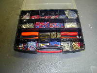
Another
"toolbox" that I have is also displayed in the attached photographs and
that is the one with all the compartments having all my various lugs.
(some people call them bits). To do wiring you will also need a
multi-meter or continuity tester to "ring out" the correct circuit. Which
Wire must I choose? A number of homebuilders are quite unsure which type
of wire to use. Make sure that your wire is rated for the ampere that you
want to transport to your various loads.
And, yes, if you can find aircraft wire
please use that and never use PVC covered wiring as used in most cars.
Proper aircraft wire is very tough and will not easily chafe and nor does
it burn well, where PVC gives of a nasty stench. (and smoke). If you can
not find aircraft wiring anywhere, go for silicone insulated wire. One
word of caution here, silicone insulation works well and does not burn,
but it is very soft and care must be taken that it does not chafe
anywhere. It must also be "suspended" more than aircraft type wire due to
the softness, but then on the other hand cable straps are quite cheap to
hold the wires in a loom.
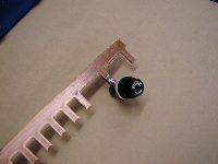
busbar construction
A very nifty
way of constructing a busbar is to use a 'fingered' copper bar that is
obtainable from your local electrical shop, as used on household
switchboards. See the attached photographs for a picture of how I have
used this in conjunction with a fuse holder.
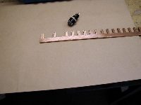
I have removed every second "tooth" on
the copper bar and that allows a nice spacing of approximately 25 mm
between fuses. Your secondary positive wire from the battery via the
master relay and ampmeter, will terminate on this bus to supply all the
loads. The positive from the alternator will also terminate here.
These
must be the only non-load wires connected to the bus ie. those from the
two power sources, namely, alternator and battery. Please connect the
alternator to this bus through a 60 amp slow blow in line fuse or suitable
DC circuit breaker. The fuse holder(s) on the load side of the positive
busbar might be substituted for a circuit breaker(s). It is best to employ
both a positive busbar and a negative. (More about this in the final
article on earthing.)
to solder or crimp the terminations?
Bad crimp connections can result in a
forced landing as recently happened to a very dear friend of mine. (who
will remain nameless for the here and now, but he did make it back to the
runway - well just!.)
To find the intermittent connection is a
mammoth task and you can spend days underneath your control panel where I
am sure you would rather fly. I have developed my own method/technique to
ensure that I have performed a good crimp and this is simply to make sure
that I have not accidentally cut off one of the wiring strands, and once I
have made the crimp I pull hard on the lug and the wire to see if they
will part. I have found that at least one in ten crimped joints will
separate and then you have to do it over again (new lug- don't use old
one), but loosing those few cents that the termination is worth, is much
hurting less than a forced landing. I still prefer to solder the lugs on.
As
you will understand the weakest point will then be where the insulation
stops and the lug body begins. To strengthen this I use a good quality
heat shrink to cover the wire and the body of the lug. See the attached
photographs to see what a good soldered termination looks like, with and
without the heat shrink insulation. Where you will be drawing heavy
current it is always best to solder, as this will prevent corrosion taking
place "inside" the crimp.
Please
also ensure that you have the correct size hole in the lug for the screw
termination on the circuit breaker or switch and never use lugs with an
open split end or of the 'push over' type. If you have to use these,
(voltage regulators are 'fond' of having this type of termination) make
sure that the wiring loom does not pull onto the wiring pin termination,
thus causing it to "pull off" and end up as a disconnection.
wiring loom separations and stringing / suspension
When I recently wired an aircraft for a
friend, I have made use of the technique where I used different looms for
different purposes, being separated and routed, where possible, along
different routes or at right angles to avoid radio interference.
So, you will say - What on earth is he
telling us. Well, make sure that you have at least the following separate
wiring looms. One for the master switch circuit, starter circuits, landing
light, nav lights and other heavy loads like under carriage or flaps,
another for the intermediate current circuits and electrical supply to the
avionics and then a totally separate loom for the intercom and
microphones/headsets. (I will discuss this in more detail in the last and
final article).
To enable me to "find my way around"
under the panel, I use various coloured cable straps for the various
looms, but this you may choose to your liking. (For the majority
production planes that I have seen, all marching on in years, you will
find all wires bundled together in a rather untidy model..) Never run your
wiring diagonally across the shortest route from one point to another, but
always parallel to the bottom of your panel or at right angles.
Make sure that you manufacture little
pillars or supports to suspend the wire looms from. I have found that RSGU
clamps work best when you want to achieve this. Also make sure that you
have enough slack in the wires that you do not get "guitar string "
vibration effects.
You can call me a liar, but I have seen
a wire like this on a plane once a couple of years ago and when you
displace this wire slightly to the side, it will make a "boing- boing"
sound. Another advantage of enough slack will be that if you want to
re-route a particular wire or connect it to another circuit, the wire will
be long enough (hopefully) and you don't have to cut all the cable straps
in the loom to get the offending wire out. Most people just give up and
splice the wire! Now, that is a dangerous practice if you don't do it
properly and needs to be avoided. Should you want to go that route, please
make sure that you use at least two layers of heat shrink isolation and
that the wire ends are twisted and soldered. However, please avoid this
technique.
summary
You now have all the tools together, you
have chosen the wire and the lug sizes, know how to perform crimps and
soldered terminations, and have planned your wiring looms and respective
routes. All that is now needed is a lot of care in performing the job.
So, you have opened the box that the
brand new intercom that you ordered at great expense from the States
arrived in, and the miniature connectors on the side looks like some
computer part and the wiring diagram is very "full". Hmmmmm, well, the
best thing to do here is read the instructions and once you have read
them, read it again. Then try and find somebody that has done this job
before and contract him/her?.
Anyway, let me explain a couple of
fundamental issues to watch out for during the installation of an
intercom.
terminations and
connections
The majority of recently designed
intercoms on the market make use of small light integrated electronic
circuits and the objective is to make it as small and light as possible.
It is for an aircraft anyway and every ounce helps, not so…. Right?
This will however present you with one
problem and that is in fact to connect it to normal wiring of the
aircraft. These small multi plug push in type connectors do not allow for
multiple wires to be soldered on, rather a multi core cable, and you thus
have to make use of an intermediate connector or circuit board. I have
found that the easiest way of doing this is to design a circuit board
(like in the back of a radio) and have the copper tracks etched, drill the
miniature holes, make your connections and mount other electrical
components like miniature relays etc. I have successfully used miniature
relays to cut out all the other mikes to the intercom during a pilot
transmission. This solely depends on the type of intercom that you have
purchased.
With the fancy voice operated intercoms,
this is not necessary or when the PPT button is activated, the intercom
disables the other mics. If you don't know which connectors will be the
best to wire your intercom ask a radio technician.
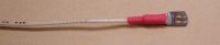
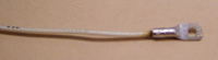
use of screen cable
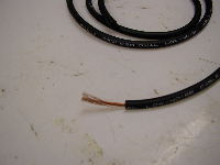
To
avoid any interference you must use screen cable on all the audio
circuits, even to the speakers of the headset. (Screen Cable is also known
as Microphone cable to some people - impedance of 75 ohms - and has a
centre core and a woven wire shield around that that acts as an electrical
shield- please see the photograph at left).
Aircraft screen cable was previously
produced with the wire shield not insulated and my recommendation will be
not to use this type, as it could lead to earthing loops etc. Even the wire to the PPT button must be a screen cable.
A good quality screen cable (woven) is
obtainable from most electronic shops and some are available with a
silicone outer shield. That is the type you must buy. (Obviously it will
also be the most expensive, but please invest in it as it is worth your
while)
single earth point
(maybe!)
Create a radio/ intercom negative bus
that is insulated form the frame of the aircraft. Yes, you have read
correctly, make sure that it is insulated and then connect this bus by
means of one heavier cable to the most suitable "earth" on the aircraft.
The negative terminal on the battery works best.
Now, where the "little" wiring diagram
that you received with your intercom shows earth points, connect all these
to this radio/intercom negative, but be careful to read the instructions
first. Some intercoms would not allow this and needs an intermediate
earth. This means that all the screen cable screens for the mics and
headset speakers get connected to a single point on the little box and
then another wire runs from the little box to your radio earth which then
connects to the battery.
What the engineers have thus done is to
put a low pass filter in the negative line to filter high frequencies from
the negative circuit. This practice is employed to prevent earth loops or
paths which "stray induced currents" can follow. The effect of these
currents would be excess noise or hum on the intercom. Another item to
watch out for is to make sure that the jack sockets (base) for the
headsets are mounted on an isolator (like Perspex) and not to the metal
frame of your plane. The negative screen is then earthed at the
intermediate point on the intercom box and not via the socket to the
aircraft frame as this will create a possible earth loop.
Following the practice described above
will get you out of trouble……well, most of the time. In Article two I have
mentioned that you must create separate wiring looms, and the intercom
cables are ideal for doing this. Keep them away from the heavy current
circuits and route them separately.
your radio needs an antenna
Your radio needs an antenna to receive
and transmit and it must be properly wired to get the best results. Hey,
you have'nt to tell me that, you will say. Well, here are a few tips.
You have a choice of antennas. You get
the quarter wave dipole one, like on most cars, aircraft, and hand held
radios, then you get a VOR type antenna, like on the tail fin of a number
of expensive aircraft (normally a V shaped wire contraption) You may use
any of these for VHF transmissions. Whichever one you have, it must still
be wired correctly, and here is how. Yet again you will need screen cable,
but with an impedance of 50 ohms with trade name RG58. (No, television
cable would not do as it has an impedance of 75 ohms…..I saw a homebuilt
the other day where the guy has in fact used television cable……..)
This cable connects to the radio by
means of a BNC connector and let me warn you, to connect the cable and the
BNC connector together takes some practice and figuring out, patience and
a steady soldering hand. Those of you who have done this before will know
what I mean. Once you have soldered it on, make sure that you don't have a
short at this connector from the centre core wire to the shield, as a
short at this point will certainly blow the class C stage of your radio
during a transmit.
When you plan the position of your VHF
antenna on the aircraft, make sure that you position it as close to the
radio as possible, as a long cable will attenuate the signal. So, to have
your antenna on the rudder, might be very fancy looking, but it might not
work all that well in practice due to the long cable. Generally, the
shorter the better.
On composite home builts you will need a
metal ground plane at the base of the antenna, at least of 50 cm in
diameter, where you use a quarter wave dipole type antenna. Make sure that
under no circumstances the ground plane can short on the rigid bare metal
antenna. If the ground plane is not earthed to the negative bus, the
shield of your antenna cable must be connected to this ground plane. (Only
composite or wooden aircraft)
Should you have a metal aircraft, make
sure that the antenna cable shield is only earthed on the radio side at
the BNC connector. This is to avoid an earth loop via the antenna cable
shield. For a metal aircraft there is no need to provide a ground plane,
as the aluminium frame acts as a ground plane. For the VOR type antenna,
the centre core of the antenna cable is connected to the "one leg" of the
V of the antenna, and the shield to the other leg. The "negative" antenna
then acts as the reflector.
You can also "tune" your antenna to the
most used frequency by making it the "exact" length. EG, say you are using
a quarter wave dipole, the length of the antenna (above the ground plane)
at 124.8 Mhz will be 60 cm.
